Tiling a large 3D-printed terrain model: jigsaw joints and dowel pins in Python
Split a 45 × 30 km model of the central Lake District into six interlocking 150 mm tiles from Copernicus GLO-30, with jigsaw knobs and a 0.2 mm printing clearance or straight edges and filament dowels, and prove every tile is watertight and fits its neighbours.
- Level
- Advanced
- Tested with
- Python 3.12
- Source code
- Download scripts
Key takeaways
- Scale the whole region once and cut the tiles from that one height grid. If each tile is scaled on its own, the seams will not meet.
- Draw the joints as an exact 2D partition first, so the tile outlines meet with no gap or overlap. Then shrink every outline by half the clearance, so that each joint ends up with the full 0.2 mm gap.
- Six jigsaw tiles came out watertight with zero overlap between them. The clearance removed 4.71 cm³ from a 1,544 cm³ model.
- Straight edges with holes for 1.75 mm filament dowels are a simpler alternative. They need no knob clearance, and the tiles stay a neat 150 mm square.
Before you start
- Python 3.10+ with numpy, rasterio, shapely, manifold3d, pyvista and matplotlib
- Part 1 of this series, From DEM to 3D-printable STL, or familiarity with building a closed mesh from a height grid
- An internet connection (the DEM is streamed from public cloud-optimised GeoTIFFs)
- A printer with a bed of at least 180 × 180 mm for the jigsaw tiles as written
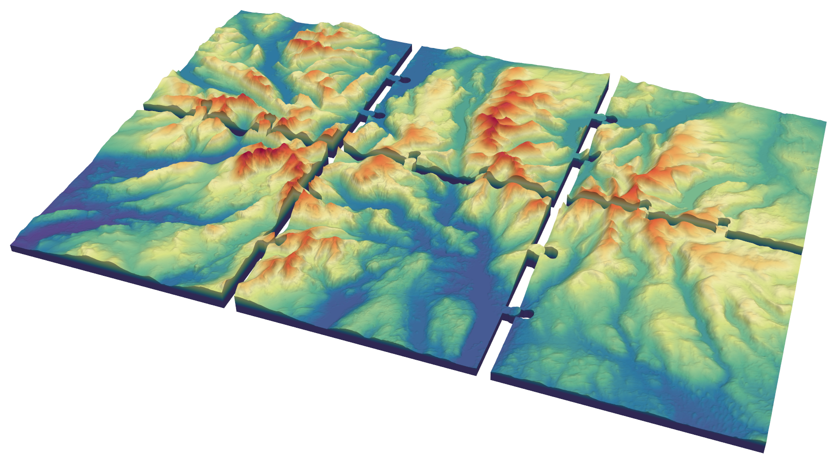
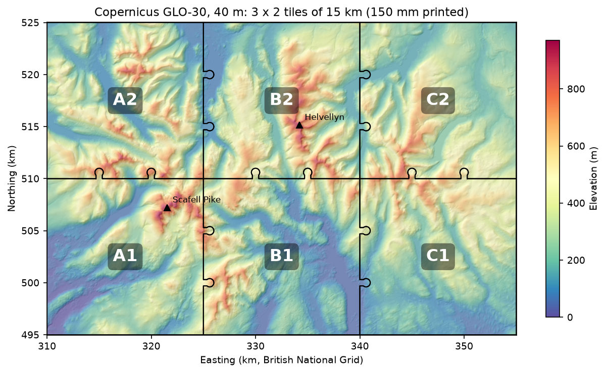
A terrain model bigger than your print bed has to be printed in tiles, and the tiles have to fit back together. That means the same scale on every tile, edges that meet exactly, and joints that lock without being too tight to assemble. This tutorial does all three in Python for a 45 × 30 km model of the central Lake District, from Scafell Pike to Helvellyn. It prints at 450 × 300 mm as six tiles of 150 mm.
Part 1 of this series, From DEM to 3D-printable STL, built one terrain solid on one print bed. Here we keep its mesh helper and add two things: 2D tile outlines drawn with shapely, and cutting with manifold3d, an exact mesh boolean library. The steps are:
- mosaic two Copernicus GLO-30 tiles onto one 40 m British National Grid;
- fix one horizontal and vertical scale for the whole model;
- draw interlocking jigsaw outlines that partition the model exactly, then open a printing clearance;
- cut six tiles, check each is watertight, and prove no two overlap;
- make an alternative set with straight edges and holes for filament dowels.
The full script is tile_terrain.py.
Step 1: one DEM from two source tiles
The Copernicus GLO-30 DEM comes in 1° tiles, and the central Lake District straddles the 3° W line, so the area needs two of them. Rather than mosaic them first and reproject afterwards, we reproject both into the same destination array. init_dest_nodata=False stops the second call from wiping out the cells the first one filled:
AOI = (310_000, 495_000, 355_000, 525_000)      # 45 x 30 km of the central Lake District, BNGRES = 40.0X0, Y0, X1, Y1 = AOICOLS, ROWS = int((X1 - X0) / RES) + 1, int((Y1 - Y0) / RES) + 1   # vertices on cell centresDST = from_origin(X0 - RES / 2, Y1 + RES / 2, RES, RES)
dem = np.full((ROWS, COLS), np.nan, dtype="float32")for url in DEM_URLS:                             # the N54 W004 and N54 W003 tiles    with rasterio.open(url) as src:        reproject(rasterio.band(src, 1), dem, dst_transform=DST, dst_crs="EPSG:27700",                  resampling=Resampling.bilinear, dst_nodata=np.nan, init_dest_nodata=False)
The grid is set up so that its cell centres fall exactly on the area’s edges, at 310,000 E, 355,000 E and so on. Each tile edge then lands on a row or column of vertices, so neighbouring tiles share heights along their seam.
=== Step 1: mosaic two GLO-30 tiles onto a 40 m grid ===Copernicus_DSM_COG_10_N54_00_W004_00_DEM.tif NaNs left: 370,380Copernicus_DSM_COG_10_N54_00_W003_00_DEM.tif NaNs left: 0grid 1126 x 751 vertices at 40 m | 0.0 - 970.8 mAfter the western tile, the cells east of 3° W are still empty; after the eastern one, none are. The highest cell is 970.8 m. Scafell Pike is 978 m, but a 30 m surface model averaged onto a 40 m grid rounds off a narrow summit.
Step 2: one scale for every tile
This is the step that makes the seams line up. Work out the scale once, for the whole model, and use it for every tile. If each tile were scaled to its own height range, as a single-tile script would do, a ridge crossing a seam would step up or down at the join:
NX, NY = 3, 2 # tiles across and upTILE_MM = 150.0scale = NX * TILE_MM / (X1 - X0) # mm per metrecell_mm = RES * scaleZ = BASE_MM + (dem - dem.min()) * scale * Z_EXAGGERATION=== Step 2: one horizontal and vertical scale for the whole model ===scale 1:100,000 | cell 0.40 mm | whole model 450 x 300 x 24.4 mm3 x 2 tiles of 150 x 150 mm = 15 x 15 km eachAt 1:100,000 each 40 m cell is 0.40 mm on the print, about one nozzle width. Finer data would add triangles but no visible detail.
Step 3: jigsaw outlines and a printing clearance
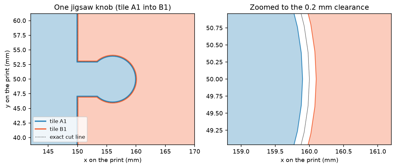
Before touching any 3D geometry, we draw the tile outlines in 2D. A knob is a 6 mm neck plus a 4 mm radius circle. Two knobs on each internal edge, a third and two thirds of the way along, stop tiles sliding or rotating against each other:
def knob(x, y, direction): """A jigsaw knob rooted on a tile edge at (x, y), pointing 'E' or 'N'.""" dx, dy = (1, 0) if direction == "E" else (0, 1) cx, cy = x + dx * KNOB_CENTRE_MM, y + dy * KNOB_CENTRE_MM half = KNOB_NECK_MM / 2 if direction == "E": neck = box(x - 0.01, y - half, cx, y + half) else: neck = box(x - half, y - 0.01, x + half, cy) return neck.union(Point(cx, cy).buffer(KNOB_R_MM, quad_segs=16))Each knob is added to one tile and subtracted from its neighbour, so the outlines still cover the model exactly once:
exact = {(i, j): box(i * TILE_MM, j * TILE_MM, (i + 1) * TILE_MM, (j + 1) * TILE_MM) for i in range(NX) for j in range(NY)}for (i, j) in list(exact): for frac in (1 / 3, 2 / 3): if i < NX - 1: k = knob((i + 1) * TILE_MM, (j + frac) * TILE_MM, "E") exact[(i, j)] = exact[(i, j)].union(k) exact[(i + 1, j)] = exact[(i + 1, j)].difference(k) # ... and the same northwardsIf you printed these exact outlines, the knobs would not go in: plastic spreads slightly wider than the model, so parts drawn to touch end up overlapping. The answer is a clearance. We shrink every outline by half of it, so each joint gets the full gap. A mitre join keeps the tile corners square:
CLEARANCE_MM = 0.2outlines = {k: p.buffer(-CLEARANCE_MM / 2, join_style="mitre") for k, p in exact.items()}=== Step 3: interlocking outlines with a printing clearance ===exact partition: sum of tile areas 135,000.000 mm2 | whole model 135,000.000 mm2 | overlap between tiles 0.000000 mm2clearance between neighbouring tiles: min 0.200 mm, max 0.283 mm over 11 jointsThe exact outlines cover the 450 × 300 mm model with no overlap. After shrinking, the closest approach between neighbours is the intended 0.2 mm. The 0.283 mm maximum is at the neck corners, where two shrunk edges meet at right angles and the gap is √2 × 0.2 mm.
Step 4: cut the tiles and prove they fit
Each tile is a heightfield solid over its outline’s bounding box (plus a cell), cut to the outline with a boolean intersection. Building only the local heightfield keeps every boolean small and fast. The vertex positions come from the same global grid, so the heights along a seam are identical on both sides:
def tile_solid(poly):    minx, miny, maxx, maxy = poly.bounds    c0, c1 = max(int(minx / cell_mm) - 1, 0), min(int(np.ceil(maxx / cell_mm)) + 2, COLS)    r0 = max(ROWS - 1 - int(np.ceil(maxy / cell_mm)) - 1, 0)    r1 = min(ROWS - int(miny / cell_mm) + 1, ROWS)    hf = to_manifold(*heightfield_solid(Z[r0:r1, c0:c1], cell_mm, c0 * cell_mm, (ROWS - r1) * cell_mm))    return hf ^ prism(poly, Z.max())          # ^ is intersection in manifold3d
tiles = {k: tile_solid(p) for k, p in outlines.items()}
prism extrudes the 2D outline into a tall column. Each tile is then checked with the same edge-count test as Part 1: every edge shared by exactly two triangles, in opposite directions. We also check every pair of tiles for overlap, and compare their total volume with the uncut model:
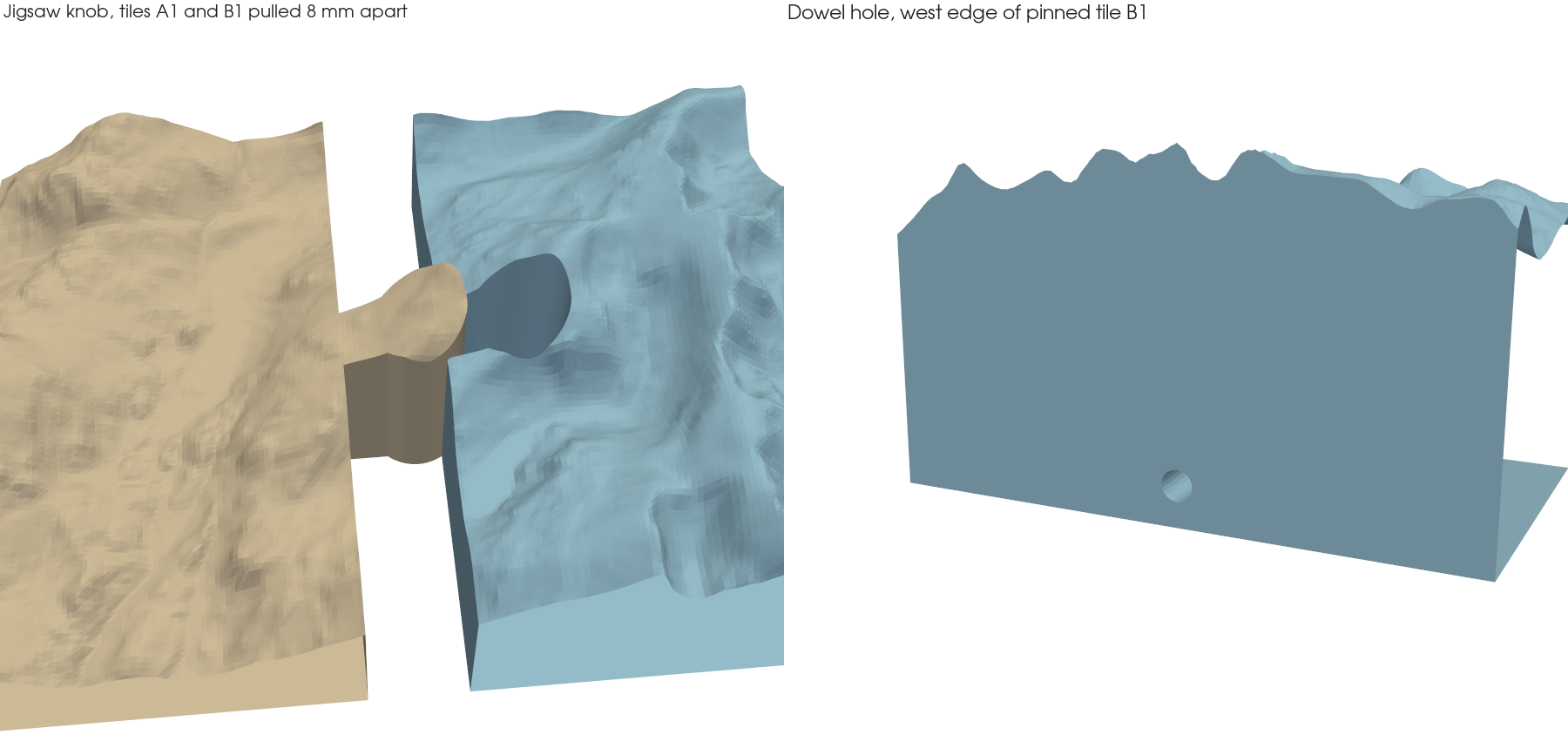
=== Step 4: cut six tiles and prove they fit ===tile A1: 573,472 triangles | watertight True | oriented True | 243.2 cm3 | footprint 159.8 x 159.8 mm, height 24.4 mmtile A2: 566,728 triangles | watertight True | oriented True | 270.5 cm3 | footprint 159.8 x 149.8 mm, height 22.8 mmtile B1: 570,664 triangles | watertight True | oriented True | 233.5 cm3 | footprint 159.8 x 159.8 mm, height 21.4 mmtile B2: 564,120 triangles | watertight True | oriented True | 282.7 cm3 | footprint 159.8 x 149.8 mm, height 23.9 mmtile C1: 566,816 triangles | watertight True | oriented True | 246.4 cm3 | footprint 149.8 x 159.8 mm, height 20.5 mmtile C2: 560,310 triangles | watertight True | oriented True | 263.1 cm3 | footprint 149.8 x 149.8 mm, height 21.5 mmpairwise overlap between tiles: 0.0000 mm3whole model 1544.08 cm3 | tiles 1539.37 cm3 | removed by the clearance 4.71 cm3All six tiles are watertight and consistently oriented, and no two overlap. The footprints show how the knobs work: tiles with knobs pointing east or north are 159.8 mm across in that direction, so a 180 mm bed takes any of them. The 4.71 cm³ difference is the thin 0.1 mm strip taken off every edge, including the outer edges of the model.
Step 5: the dowel-pin alternative
Jigsaw knobs are satisfying, but they make some tiles 10 mm larger and mean the tiles can only be assembled in one direction. A simpler option is straight edges with holes for short dowels. Plain 1.75 mm filament, cut to length, makes good dowels, so we drill 1.9 mm holes 10 mm into each side of every joint, halfway up the 5 mm base:
PIN_HOLE_D_MM, PIN_DEPTH_MM = 1.9, 10.0
def pin_hole(x, y, axis):    cyl = mf.Manifold.cylinder(2 * PIN_DEPTH_MM, PIN_HOLE_D_MM / 2, circular_segments=24, center=True)    cyl = cyl.rotate((0, 90, 0)) if axis == "x" else cyl.rotate((90, 0, 0))    return cyl.translate((x, y, BASE_MM / 2))
all_holes = mf.Manifold.batch_boolean(holes, mf.OpType.Add)pinned = {k: tile_solid(sq.buffer(-CLEARANCE_MM / 2, join_style="mitre")) - all_holes          for k, sq in squares.items()}
Each hole is one cylinder spanning the joint, so the two halves line up exactly. One batch_boolean merges all 14 cylinders, and one subtraction per tile cuts them.
=== Step 5: straight edges with holes for filament dowels ===14 dowels, each 19.8 mm long; every pinned tile watertight and oriented: Truepin holes per tile: A1 4, A2 4, B1 6, B2 6, C1 4, C2 4plastic above and below each hole: 1.55 mmThe dowel length allows for the 0.2 mm gap. The 1.55 mm of plastic above and below each hole is enough for a 5 mm base; if you thin the base, keep at least 1 mm.
Printing tips
- Print every tile with the same settings and filament. A change of layer height or brand between tiles shows as a visible change in surface texture.
- Watch the first layer. Elephant’s foot, where the first layer squashes outwards, closes up the clearance at the bottom of the joint. Use your slicer’s elephant foot compensation, or chamfer the base.
- Dowel holes print sideways. A horizontal 1.9 mm hole sags slightly at the top. If dowels will not go in, run a 2 mm drill bit through by hand rather than enlarging every hole in the model.
- Glue is optional. Jigsaw tiles hold together without glue for display, and can be taken apart for transport. For a permanent piece, a little glue on the knobs or dowels is plenty.
- Seams sit on the terrain. Place the cut lines away from summits or famous features where you can, by moving
AOIby a kilometre or two.
Limitations
- GLO-30 is a surface model. It includes trees and buildings, and at 40 m it rounds off crags. It is ideal for a regional model like this one; for a single fell at a larger scale, use Environment Agency LiDAR instead.
- The clearance is a starting point. 0.2 mm worked as a design value here, but the right figure depends on your printer, nozzle and filament. Test a small piece first.
- Lakes are not flattened. Lake surfaces appear as they do in the DEM, which is mostly flat but not perfectly level. Part 3 shows how to lower lakes and print them in a separate colour.
Frequently asked questions
How do I 3D print a map bigger than my print bed?
Split it into tiles that each fit the bed, cut from one height grid at one scale, and join them with jigsaw knobs or dowel pins. Leave a small clearance between parts, about 0.2 mm, so they fit together after printing. This tutorial’s script does the cutting and checks every tile is watertight.
What clearance should I use for 3D-printed jigsaw joints?
Between 0.1 and 0.3 mm in total suits most FDM printers with a 0.4 mm nozzle; 0.2 mm is a sensible start. Shrink each part by half the clearance so the full gap appears at every joint, and test on a small piece before printing large tiles.
Why don’t my terrain tiles line up at the seams?
Usually because each tile was scaled on its own height range, or because the tiles were cut from separately resampled rasters. Scale the whole region once and cut every tile from the same grid, so both sides of a seam share exactly the same heights.
Should I use jigsaw joints or dowel pins?
Jigsaw knobs need no extra parts and lock tiles together sideways, but they make some tiles 10 mm larger and fix the assembly order. Dowel pins keep the tiles square and interchangeable, but you need to cut 14 short pieces of filament and the joints only resist pulling apart once glued.
Can I make more or larger tiles?
Yes. Change NX, NY and TILE_MM, and adjust AOI to match the shape. The script works out the scale from the area and the number of tiles across, so everything else follows.
Next steps
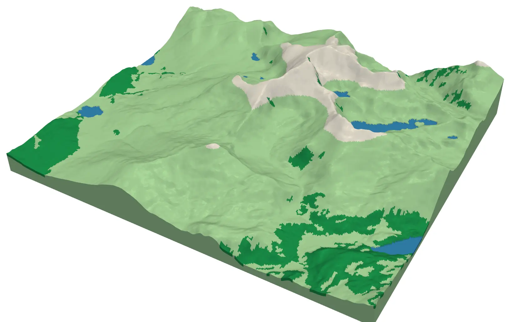
- Add colour tile by tile: Part 3, multi-colour terrain prints, splits terrain into one STL per colour, and the same cut works on each tile.
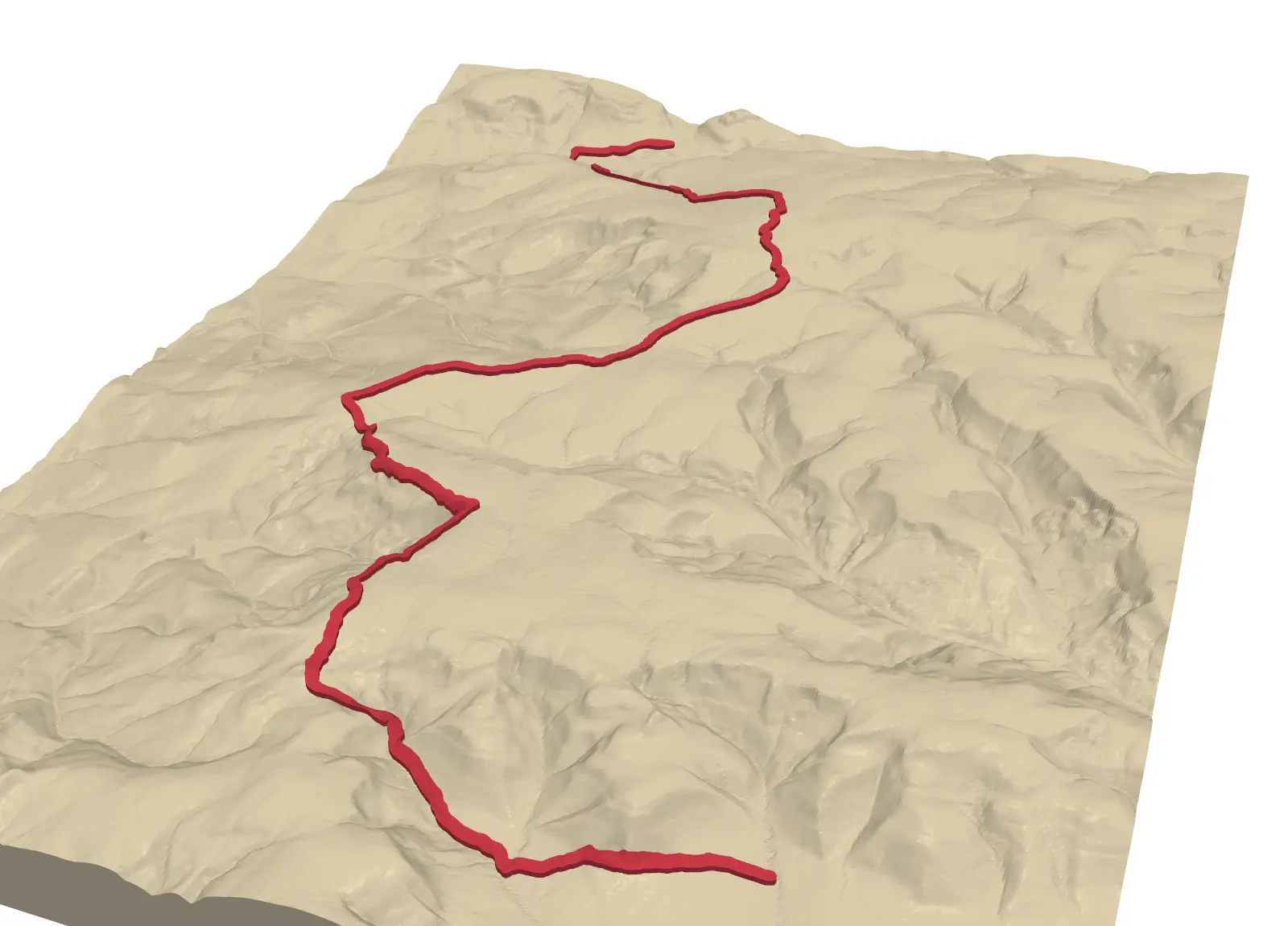
- Mark a long walk across the tiles: Part 2, GPX route on 3D-printed terrain, embosses or engraves a route into the terrain.
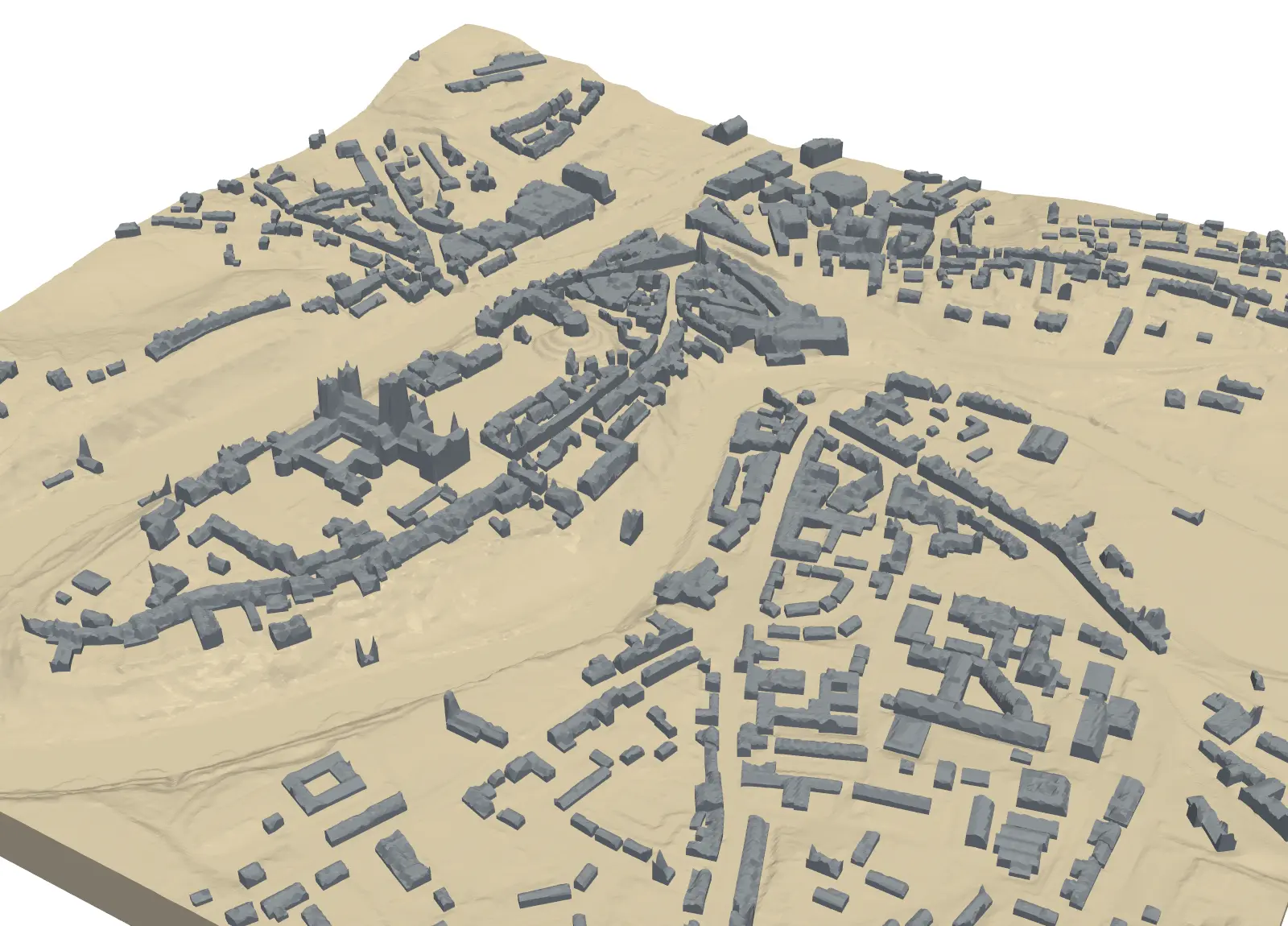
- Print a town at a much larger scale: Part 4, a 3D-printed city model.
- Prefer a desktop GIS? Creating a 3D-printed DEM in QGIS covers the single-tile workflow without code.
Data and licences
- Copernicus DEM GLO-30: © DLR e.V. 2010–2014 and © Airbus Defence and Space GmbH 2014–2018, provided under COPERNICUS by the European Union and ESA; all rights reserved. Accessed from the AWS Open Data registry.
- Code:
tile_terrain.py, tested with Python 3.12.0, numpy 2.5.4, rasterio 1.5.2, shapely 2.2.0, manifold3d 3.5.5 and pyvista 0.49.2. All processing runs locally; the only network requests read the two public DEM tiles.
Key terms
- Clearance
- A deliberate gap between two printed parts that must fit together. It allows for the plastic spreading slightly wider than the model, so 0.1 to 0.3 mm is typical for FDM printers.
- Partition
- A set of shapes that cover an area exactly once: their union is the whole area and no two of them overlap.
- Mitre join
- When a polygon is shrunk (negatively buffered), a mitre join keeps its corners sharp instead of rounding them, so square tile corners stay square.
- Dowel
- A short peg that fits into matching holes in two parts to align them. Plain 1.75 mm filament, cut to length, makes a cheap dowel.
Data for this tutorial
- Copernicus DEM (GLO-30 / GLO-90) · Global 30 m elevation, free with attribution
- GIS data sources for the United Kingdom
Licences and formats for each source are listed in the GIS data sources catalogue.